10+ dc block diagram
Pwaste 500W090 500W 5555W 500W 555W. Up to 24 cash back On the left side there is a library vertical bar from there drag and drop the block shape onto the main project.
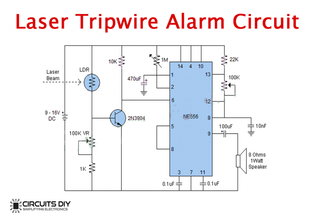
Top 10 Simple Electronics Projects For Complete Beginners
The resistance transducers like strain.

. Drives can be classified as DC Drives and AC Drives In this lecture we shall consider DC drives only. The load may be connected across the. Create and label the diagram.
Avsofts McDonnell Douglas DC-10-30 System Diagrams poster set includes the following DC-10-30 aircraft system diagrams. The block diagram of dc. But with backward movement p will become X s.
Add a symbol for each. Best Practices Identify the system. Per the examples above by employing a more efficient power converter it reduces.
It is shown in block diagram form in Figure 94. Innovations in Intel Stratix 10 FPGAs and SoCs 13. Power Supply block Diagram.
Only two of the elements in the diagram the TMR2 register and the prescaler actually relate. Intel Stratix 10 FPGA and SoC Family Plan 16. The block diagram of a regulated DC power supply is shown in above figure.
Intel Stratix 10 Block Diagram 15. It consists of rectifier filter and voltage regulator circuits. FPGA and SoC Features Summary 14.
Signal conditioning system is shown in the Fig. Here p X sG s. Determine the system to be illustrated.
Pwaste Poutη Pout. The 16F87XA Timer 2 is a simple 8-bit device. Our block diagram maker is the ideal diagramming solution to help engineers tackle complex system overviews when designing hardware or software.
Air Conditioning Electrical Fuel Hydraulic. In order to move the take-off point behind the block we need to keep the value of p same. So we have to add another.
In order to achieve a direct current voltage source the alternating current input must follow a conversion process like the one shown in the power supply block diagrambelow. You can use the green selection handles to tailor the. The resistance transducers are commonly used for the dc.
Power Semiconductor Drive and its Elements The basic arrangement of an electrical. Define components inputs and outputs.

Solved 1 P5 79 Hybrid Vehicle Figure P5 53 Shows The Chegg Com

Paper Toys Template Person Template Paper Crafts

10 Practical Examples Of Open Loop Control System Etechnog

Atx Power Supply Pinout Diagram And Connector 20 24 Pin Etechnog
715s 20 1 950 100 Watts 1 700 2 600 Ghz Meca Electronics Inc
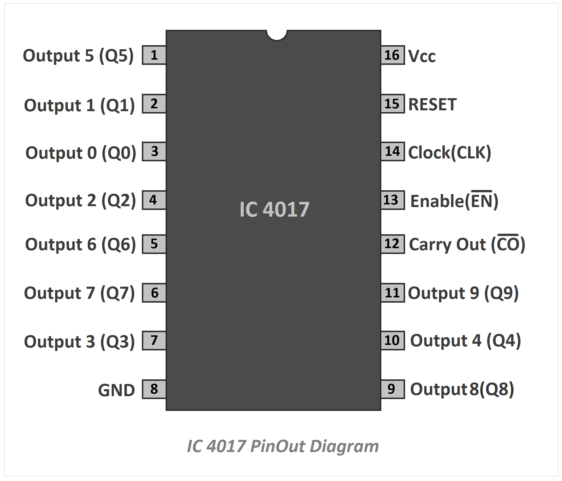
Ic 4017 Pinout Diagram And Terminal Identification Etechnog

Home Electrical Wiring Bathroom Exhaust Fan Outlet Wiring
Could You Review My Wiring Diagram Ram Promaster Forum
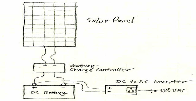
Solar Power System Diagram 4 Basic Building Blocks
Diagram For My 12v Puck Lights Ram Promaster Forum

Is 0 900 10 Watts Sma Female 0 800 1 000 Ghz Meca Electronics Inc
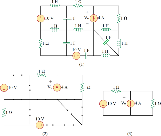
Solutions Of Problems Second Order And Higher Order Circuits Springerlink
1

Diy Flowers Video Paper Flowers Craft Paper Crafts Paper Flowers

10 Multiple Effect Evaporator Diagram Of Multiple Effect Evaporator Pharmacy Images Medicine Images Free Human Body

Purpose Of Inductor And Capacitor In A Circuit Inductor Capacitor Circuit

10 General Electric Furnace Wiring Diagram Electrical Diagram Electric Furnace Washing Machine Motor